Battery Pack Requirements for Cordless Vacuum Cleaners
The cordless vacuum cleaner has become one of the most demanding battery-powered appliances in the modern home. Unlike a drill that delivers short bursts of power, a stick vacuum can draw sustained high current for 15 to 60 minutes of continuous operation, pushing the motor, air path, and battery pack toward their thermal and electrical limits at the same time.
A cordless vacuum cleaner battery pack is therefore not simply a larger power-tool battery. It must provide sustained high-current output, support hundreds of deep cycles, fit within a tightly engineered handle or stick body, and meet the safety requirements expected of a consumer lithium-ion product.
For battery pack engineering, the starting point should be the application load rather than battery capacity alone. Motor demand, discharge current, target runtime, voltage platform, thermal conditions, mechanical envelope, charger requirements, and protection strategy all need to be evaluated together.
This article examines the main requirements for a lithium-ion battery pack for cordless vacuum cleaners, from cell selection and voltage configuration to BMS design, thermal management, runtime planning, production testing, and OEM/ODM project validation.

Why Cordless Vacuums Need High-Discharge Battery Packs
A typical cordless drill draws peak current for only a few seconds per trigger pull. A cordless stick vacuum, by contrast, runs its brushless motor continuously throughout the cleaning session.
Modern cordless vacuums commonly feature brushless DC (BLDC) motors operating at approximately 80,000 RPM in entry-level designs and up to around 150,000 RPM in higher-performance products, with suction power ranging from roughly 100 AW to more than 250 AW.
This creates a continuous discharge load that the cordless vacuum battery must sustain without excessive voltage sag. Motor power consumption commonly falls between 200 W and 800 W depending on operating mode and product tier.
At a 25.2 V nominal bus, for example, sustained battery discharge current may range from approximately 8 A to more than 30 A in turbo mode. The battery pack must maintain its voltage under this load because excessive voltage sag can reduce motor RPM and, consequently, suction performance.
The key electrical demands can be summarized as follows:
| Requirement | Typical Range | Engineering Implication |
|---|---|---|
| Nominal voltage | 14.4 V–25.2 V (4S to 7S Li-ion) | Determines the motor power platform and must match the device bus voltage |
| Capacity | 2.0 Ah–5.0 Ah | Directly affects runtime and available energy per charge |
| Continuous discharge | 10 A–30 A+ | Must support high-power operation without falling below the system cutoff voltage |
| Cycle life | 300–500 full cycles | Influences usable product life under repeated charging and deep discharge |
| Operating temperature | Charge 0–45°C; discharge –20–60°C | The pack must tolerate ambient heat and heat generated by the motor and battery itself |
The important engineering point is that voltage and Ah alone do not define a suitable cordless vacuum cleaner battery pack. Continuous current, peak current, voltage sag, thermal behavior, and protection thresholds must also match the actual vacuum load. For a deeper explanation of how amp-hour ratings influence usable energy and operating time, see this guide to battery capacity and runtime.
Choosing 18650 or 21700 Cells and Battery Chemistry
The vast majority of cordless vacuum battery packs use cylindrical 18650 or 21700 lithium-ion cells in a series-parallel arrangement.
The 18650 format measures approximately 18 mm in diameter and 65 mm in length. It has been widely used for years and offers a mature supply chain, established manufacturing processes, and energy density of approximately 250 Wh/kg for vacuum applications.
The newer 21700 format, at approximately 21 mm in diameter and 70 mm in length, can provide roughly 30–50% more capacity per cell. This can reduce the number of cells required to reach a particular battery capacity, although the larger cell dimensions must be considered during mechanical design. A practical example is a 25.2V high-capacity 21700 cordless vacuum battery pack, which illustrates how the 21700 format can be applied in a compact vacuum battery platform.
Two cathode families are commonly considered for cordless vacuum battery applications:
| Chemistry | Energy Density | Discharge Rate | Cycle Life | Typical Use Case |
|---|---|---|---|---|
| NCM (Nickel-Cobalt-Manganese) | High (~250 Wh/kg) | High, up to approximately 10C burst | 300–500 cycles | Mainstream cordless vacuums where size, weight, and energy density matter |
| LiFePO4 (Lithium Iron Phosphate) | Lower (~160 Wh/kg) | Very high, up to approximately 20C | 1,000+ cycles | Industrial or heavy-duty applications prioritizing safety and cycle life |
NCM cells are widely used in consumer cordless vacuum packs because they provide a practical balance between energy density and cost. This is particularly important when the battery must fit inside a slim stick body without adding excessive weight.
LiFePO4 chemistry is heavier and bulkier at the same energy capacity but may be considered for commercial or industrial applications where long cycle life and thermal stability take priority over minimum size and weight.
Cell matching is also critical. Cordless vacuum battery packs commonly use five to seven cells in series:
- 5S = approximately 18.5 V nominal
- 6S = approximately 22.2 V nominal
- 7S = approximately 25.9 V nominal
If one cell begins to drift significantly in capacity or internal resistance, it can limit the usable capacity of the entire pack. The BMS may stop discharge when the weakest cell reaches its low-voltage threshold—typically around 2.5 V to 2.8 V—even when other cells still contain usable energy.
For this reason, pack manufacturers commonly grade and match cells before assembly, with capacity matching typically within ±1% and internal resistance within approximately ±5 mΩ.
Cell selection should therefore consider not only nominal capacity but also discharge capability, internal resistance, consistency, thermal behavior, mechanical space, and expected cycle life.
Matching Battery Voltage, Interface, and Communication
Cordless vacuum battery packs operate across several voltage platforms, and the battery voltage must match the device motor-controller requirements. The same principle applies across many cordless battery systems: battery voltage and platform matching must be confirmed before capacity or performance upgrades are considered.
Typical configurations include:
| Series Configuration | Nominal Voltage | Common Cell Count | Typical Application |
|---|---|---|---|
| 4S | 14.8 V | 4 × 18650, 4S1P or 4S2P | Handheld, automotive, or lower-power stick vacuums |
| 5S | 18.5 V | 5 × 18650, 5S1P or 5S2P | Mid-range stick vacuums and similar compact platforms |
| 6S | 22.2 V | 6 × 18650, 6S1P or 6S2P | Mainstream cordless stick vacuums |
| 7S | 25.9 V | 7 × 18650, 7S1P or 7S2P | Higher-power cordless vacuums and 25.2 V-class systems |
The 6S and 7S configurations are common in modern cordless stick vacuums. Some mainstream platforms use approximately 25.2 V lithium-ion systems, while other designs use five- or six-cell series packs.
A 21.6V 2Ah 6S1P cordless vacuum replacement battery provides one example of how a six-cell series configuration can be packaged for a vacuum application. Other products may use a broader 21.6V–25.2V cordless vacuum cleaner battery range depending on the target appliance and battery architecture.
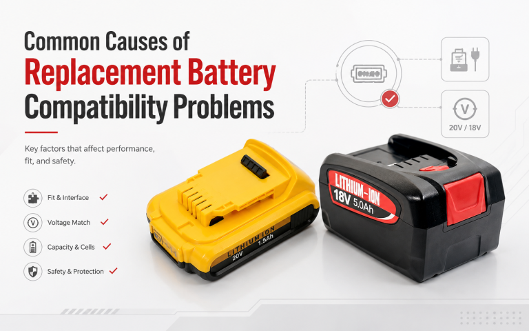
For a replacement vacuum cleaner battery, however, matching voltage is only one compatibility requirement.
Many premium cordless vacuum platforms include additional battery terminals for identification, temperature sensing, state-of-charge reporting, or communication with the appliance main board. A replacement battery that provides the correct voltage but does not support the expected communication or terminal arrangement may be rejected by the device or may produce inaccurate battery-level information.
A project should therefore determine whether the system uses:
- A simple two-terminal interface such as P+ and P–
- Additional temperature-sensing terminals
- A multi-terminal smart battery interface
- A communication protocol between the battery and host device
- A specific charger-to-BMS relationship
Mechanical compatibility must be checked separately from electrical compatibility. Pack dimensions, mounting features, enclosure shape, locking mechanism, terminal position, connector geometry, and charger fit can all prevent an otherwise electrically suitable battery from working correctly. These issues are explored in more detail in the guide to battery interfaces and contact compatibility.
For this reason, GeB Power’s battery project review process considers voltage, application load, interfaces, connectors, enclosure requirements, protection requirements, charging conditions, and mechanical fit together rather than confirming compatibility from voltage or a product name alone. Buyers dealing with an existing platform can also review common battery compatibility problems before approving a replacement design.

What the BMS Must Do in a Cordless Vacuum Battery Pack
After the cells themselves, the Battery Management System is one of the most important elements of a cordless vacuum battery pack.
A BMS for this application generally needs to manage four primary functions.
1. Overcharge and Overdischarge Protection
Each cell must be monitored so that the pack remains within its allowable voltage range.
Overcharge above approximately 4.25 V per cell can increase safety risk, while excessive discharge below approximately 2.50 V per cell can cause irreversible capacity loss. The BMS therefore needs to disconnect the charge or discharge path when defined thresholds are reached.
2. Cell Balancing
Cells within a 6S or 7S battery pack naturally drift over repeated charge and discharge cycles.
Passive balancing, where excess cell energy is dissipated through a resistor, is widely used in consumer battery packs. Typical balancing current may be approximately 30–50 mA, which can be suitable for battery packs charged over three to five hours.
Active balancing can redistribute energy more efficiently but is less common in cost- and space-sensitive consumer vacuum battery packs.
3. Overcurrent and Short-Circuit Protection
Vacuum motors can experience temporary current spikes when the nozzle or brush encounters an obstruction.
The BMS may therefore need to tolerate short transient spikes—for example, 40–50 A for approximately 100 ms—while disconnecting sustained overcurrent above the pack’s rated continuous discharge capability.
Short-circuit protection must operate much more quickly to reduce the risk of severe electrical and thermal damage.
4. Thermal Protection
NTC thermistors are commonly used to monitor battery pack temperature.
Charging may be suspended above approximately 45°C or below 0°C, while discharge may be limited or stopped at temperatures around 60°C depending on the pack design.
Thermal protection is particularly important in a cordless vacuum cleaner because the motor and battery are often positioned close together.
Some battery packs also integrate a dedicated fuel-gauge IC that uses coulomb counting to estimate state of charge. This allows an appliance display to provide more accurate remaining-runtime information rather than relying only on a simple voltage-based battery indicator.
For a custom vacuum cleaner battery pack, the project specification should define whether the fuel gauge communicates through I2C, SMBus, or another interface and whether the host appliance expects particular battery data.
Managing Heat and Building the Battery Pack
Thermal management is one of the most important challenges in cordless vacuum battery pack design.
In many vacuum designs, the motor is positioned only centimeters away from the battery. The air path carrying motor waste heat may also pass near the battery compartment.
During a 30-minute turbo-mode cleaning session, pack surface temperatures can reach approximately 45–55°C even without additional external heat sources.
Effective battery thermal management can involve several construction techniques:
| Technique | Purpose | Typical Implementation |
|---|---|---|
| Cell-to-cell spacing | Reduce thermal transfer between adjacent cells | 1–2 mm gaps or thermal insulation pads |
| Nickel strip gauge | Carry high discharge current without excessive resistive heating | Approximately 0.15 mm × 8 mm nickel strips minimum, with parallel paths for higher-current packs |
| Thermal sensor placement | Detect localized heating | NTC positioned near a high-impedance cell or pack center |
| Ventilation channels | Support convective cooling | Molded ribs or air gaps within the housing |
| Potting or conformal coating | Protect the BMS PCB from dust and moisture | Selective protection around the BMS area |
The housing must satisfy both thermal and mechanical requirements.
Vacuum battery packs are commonly enclosed in ABS or PC/ABS blend plastic, with approximately 1.5 mm minimum wall thickness used in designs intended to withstand drop testing.
The enclosure may also require a controlled venting feature, such as a designed weak point or vent membrane, so that gas can be released in the event of cell venting rather than building pressure inside the housing.
This illustrates why a larger battery is not automatically a better battery for a cordless vacuum. Battery pack engineering must balance runtime, discharge power, weight, pack dimensions, temperature, mechanical strength, and cost within the space available in the appliance.
How to Size Battery Capacity for Cordless Vacuum Runtime
Runtime is one of the most visible performance metrics for cordless vacuum users, but it cannot be evaluated from Ah capacity alone.
Actual runtime depends on:
- Battery voltage
- Battery capacity
- Motor power
- BMS and wiring losses
- Operating mode
- Discharge efficiency
- Temperature
- Cell voltage sag under load
A simplified runtime estimate can be expressed as:
Runtime (min) = [Pack Capacity (Wh) × 60 × η] ÷ Motor Power (W)
where η is the overall efficiency factor, typically around 0.75–0.85, accounting for BMS losses, wiring resistance, and motor-driver efficiency.
For a typical 7S pack with seven 2500 mAh cells:
25.9 V × 2.5 Ah = 64.75 Wh
When powering a 300 W motor in standard or high-power operation:
Runtime = (64.75 × 60 × 0.80) ÷ 300 ≈ 10.4 minutes
In an eco mode drawing approximately 120 W, the same battery pack can deliver roughly 26 minutes.
This is why cordless vacuum manufacturers may quote runtime ranges of approximately 10–60 minutes depending on operating mode. The battery capacity remains the same, but the discharge rate can vary by a factor of two to three between modes.
For replacement battery applications, increasing capacity can extend runtime. Moving from 2000 mAh to 3000 mAh cells in the same 7S1P configuration represents a 50% increase in nominal capacity and can provide a corresponding increase in available runtime, provided that the cells meet the required discharge characteristics, fit within the existing mechanical envelope, and remain compatible with the BMS.
The better engineering question is therefore not simply:
“What Ah battery should this vacuum use?”
It is:
“What battery pack can deliver the required runtime at the actual operating load while remaining within the electrical, thermal, and mechanical limits of the product?”
Safety Standards and Certification for Cordless Vacuum Batteries
Cordless vacuum battery packs are consumer lithium-ion products, and the applicable safety and transportation requirements depend on the battery configuration, product, destination market, and shipping method.
Common requirements may include:
| Standard | Scope | Market | Key Tests |
|---|---|---|---|
| UL 2054 | Household and commercial battery packs | North America | Short circuit, overcharge, forced discharge, crush, impact, vibration, temperature cycling |
| IEC 62133-2 | Portable sealed secondary lithium cells and batteries | International | External short circuit, free fall, thermal abuse, overcharge, forced discharge |
| UN 38.3 | Transportation safety for lithium batteries | Global shipping | Altitude, thermal, vibration, shock, short circuit, impact, overcharge, forced discharge |
| EU Electromagnetic Compatibility (EMC) requirements | Electromagnetic compatibility | EU | Emissions and immunity relevant to electronic control circuits |
| FCC Part 15 | Radio-frequency emissions | USA | Unintentional-radiator requirements relevant to electronic circuits |
UL 2054 deserves particular attention for battery packs intended for the North American market. It evaluates the complete assembled battery pack rather than only the individual lithium-ion cells.
The standard evaluates system-level safety factors such as protection-circuit response, inter-cell connection integrity, enclosure strength, and resistance to safety-related failure conditions.
For OEM/ODM battery projects, certification work typically follows a sequence such as:
- Design review — Pack schematic, BOM, cell specifications, and structural drawings are prepared for laboratory review.
- Sample preparation — Production-representative samples are built using the intended cells, BMS, and enclosure.
- Testing — The laboratory performs the required tests, which may take approximately 6–12 weeks depending on the standard and laboratory capacity.
- Report and listing — Successful testing results in the applicable test report or listing process.
A change to the cell model, BMS IC, or enclosure after certification may require additional review or re-testing. Cell selection and critical BMS design parameters should therefore be stabilized before formal certification work begins.
Battery documentation should also be treated as model- and configuration-specific rather than as a generic checkbox. The applicable certificates, test reports, safety data, UN38.3 documentation, and shipping documents can vary according to battery configuration, transport mode, and destination market. For air shipments in particular, buyers should verify the applicable lithium battery air transport requirements for the final product and shipping route.

Production Testing and Quality Control
Certification establishes an important safety baseline, but consistent mass-production quality determines whether battery packs continue to meet the approved specification.
Typical production tests for cordless vacuum battery packs include:
| Test | Purpose | Typical Threshold |
|---|---|---|
| OCV matching | Ensure cells have similar SOC before assembly | Within approximately 20 mV |
| Internal-resistance sorting | Match cells for balanced discharge behavior | Within approximately 5 mΩ |
| Weld-strength test | Verify nickel-to-cell connection integrity | ≥50 N pull force |
| PCM/BMS functional test | Confirm protection triggering | Overcharge cutoff around 4.25 ± 0.05 V per cell |
| Aging / cycling test | Detect early performance failures | 50 cycles at 0.5C with <5% capacity loss |
| Drop test | Verify mechanical integrity | 1.0 m onto concrete, six faces, no fire or leakage |
A robust production process may also include full-pack end-of-line testing. Each completed battery can be charged, discharged at a representative load such as 1C, and checked to verify that delivered capacity meets specification within approximately ±3%.
Units that do not meet the defined acceptance criteria should be separated for investigation rather than continuing directly into shipment.
For B2B battery projects, quality control should be tied to an approved project specification rather than treated as the same fixed checklist for every battery. Inspection points, acceptance requirements, labels, packaging, and production records should be defined according to the selected battery configuration and the customer’s project requirements.
What to Define Before Starting an OEM/ODM Vacuum Battery Project
For brand customers, product teams, and engineers evaluating an OEM/ODM cordless vacuum battery pack, project success depends heavily on how clearly the requirements are defined before tooling and production.
Freeze the key specifications early. Late changes to cell capacity, battery dimensions, connectors, or BMS functionality can delay tooling, validation, documentation, and production planning.
The electrical specification should define:
- Nominal voltage
- Target capacity
- Continuous discharge current
- Peak discharge requirement
- Protection thresholds
- Charging requirements
- Communication or fuel-gauge requirements
The mechanical specification should define:
- Battery envelope dimensions
- Housing requirements
- Connector type
- Terminal layout
- Mounting and locking features
- Pack removal requirements
- Weight targets
These two groups of requirements should be reviewed separately and then validated together. An electrically suitable battery may still fail because of enclosure dimensions, terminal position, connector geometry, charger fit, or installation method.
Define the sample validation protocol. A suitable validation process can include electrical performance testing, discharge-curve analysis, cycle-life evaluation, temperature testing, humidity exposure, mechanical checks, drop testing, actual-vacuum runtime verification, and charging compatibility.
For application-specific battery development, a practical project path is:
Application Review → Pack Engineering → Sample Validation → Production Handoff
This approach converts the buyer’s application requirements into a defined battery specification before production. The principle is simple: proof before production.
GeB Power provides custom battery project support, application review, pack engineering, sample validation, and document review for B2B OEM/ODM projects. The process connects application load, voltage, target capacity, interface, connectors, enclosure, protection requirements, working environment, validation expectations, and production requirements before project handoff.
Define the documentation scope before shipment. Depending on the battery configuration and market, the documentation package may include cell specifications, battery test reports, safety data sheets, UN38.3-related documents, assembly information, and transportation documents.
The exact document set should be confirmed for the final battery model, configuration, shipping route, and destination rather than assumed during early product selection.
For an efficient custom cordless vacuum battery pack RFQ, buyers should ideally provide:
- Vacuum cleaner application or model
- Existing battery reference, if applicable
- Nominal voltage
- Motor power or load information
- Operating modes
- Target runtime
- Required battery capacity
- Continuous and peak discharge requirements, if known
- Charger information
- Connector and terminal requirements
- Available battery dimensions
- Housing requirements
- Working environment
- Expected order quantity
- Destination market
- Label and packaging requirements
- Required certificates, test reports, or shipping documents
Providing this information early helps the battery supplier determine whether an existing battery platform can be used or whether a dedicated OEM/ODM battery pack engineering project is required.
Conclusion
A cordless vacuum cleaner battery pack must be designed as a complete system rather than selected from voltage and capacity alone. Cell chemistry, discharge capability, battery capacity, BMS protection, thermal management, mechanical fit, charger compatibility, runtime requirements, safety documentation, and production validation all influence whether the battery performs reliably in the finished appliance.
The most effective approach is to start with the actual vacuum load and intended runtime, define the electrical and mechanical requirements together, and validate the battery in the intended device before production. For OEM/ODM programs, this reduces the risk of discovering compatibility, temperature, runtime, or documentation problems after the design has already been committed.
GeB Power supports global B2B buyers with application review, battery pack engineering, sample validation, structured production handoff, and document review for application-specific OEM/ODM battery projects. Contact GeB Power to discuss your cordless vacuum cleaner battery pack requirements, including voltage, load, runtime, interface, quantity, destination market, and required documentation.
FAQ
What voltage is commonly used in a cordless vacuum cleaner battery pack?
Cordless vacuum cleaner battery packs commonly use configurations ranging from approximately 14.4 V to 25.9 V, including 4S, 5S, 6S, and 7S lithium-ion architectures. The correct voltage must match the vacuum’s motor controller, charger, BMS, and electrical interface rather than being selected independently.
How much battery capacity does a cordless vacuum need?
Typical cordless vacuum battery capacities range from approximately 2.0 Ah to 5.0 Ah, but the required capacity depends on motor power, operating mode, voltage, discharge efficiency, target runtime, available pack space, and weight limits. Capacity should therefore be calculated from the application load and runtime requirement rather than selected from Ah alone.
Are 18650 or 21700 cells better for cordless vacuum batteries?
Both formats can be suitable. 18650 cells provide mature availability and compact dimensions, while 21700 cells can offer approximately 30–50% more capacity per cell. The better choice depends on energy requirement, discharge current, available space, pack weight, thermal design, and cost.
What protection does a cordless vacuum battery BMS need?
A cordless vacuum battery BMS commonly manages overcharge, overdischarge, overcurrent, short-circuit, and temperature protection. Depending on the design, it may also provide cell balancing, state-of-charge estimation, temperature sensing, and communication with the vacuum’s main controller.
What information should I provide for an OEM cordless vacuum battery project?
Provide the application or vacuum model, nominal voltage, load or motor power, target runtime, capacity, discharge requirements, charger information, connector and interface, available pack dimensions, housing requirements, quantity, destination, and required documentation. These inputs allow the battery pack to be reviewed from electrical, mechanical, thermal, and production perspectives.
Appendix: Sources
- Cordless vacuum cleaner product specifications — public product reference.
- Cordless vacuum cleaner performance specifications — public product reference.
- Smart vacuum cleaner lithium battery and 18650 cell specifications — public technical reference.
- Cordless vacuum lithium battery runtime degradation and repair guide — industry technical article.
- 25.2 V cordless vacuum product specifications — public retail product reference.
- 18650 lithium-ion cell applications in cordless vacuum products — battery industry reference.
- UL 2054 Standard for Safety: Household and Commercial Batteries — standards reference material.
- UL 2054 household and commercial battery safety standard — technical standards analysis.